
 EN



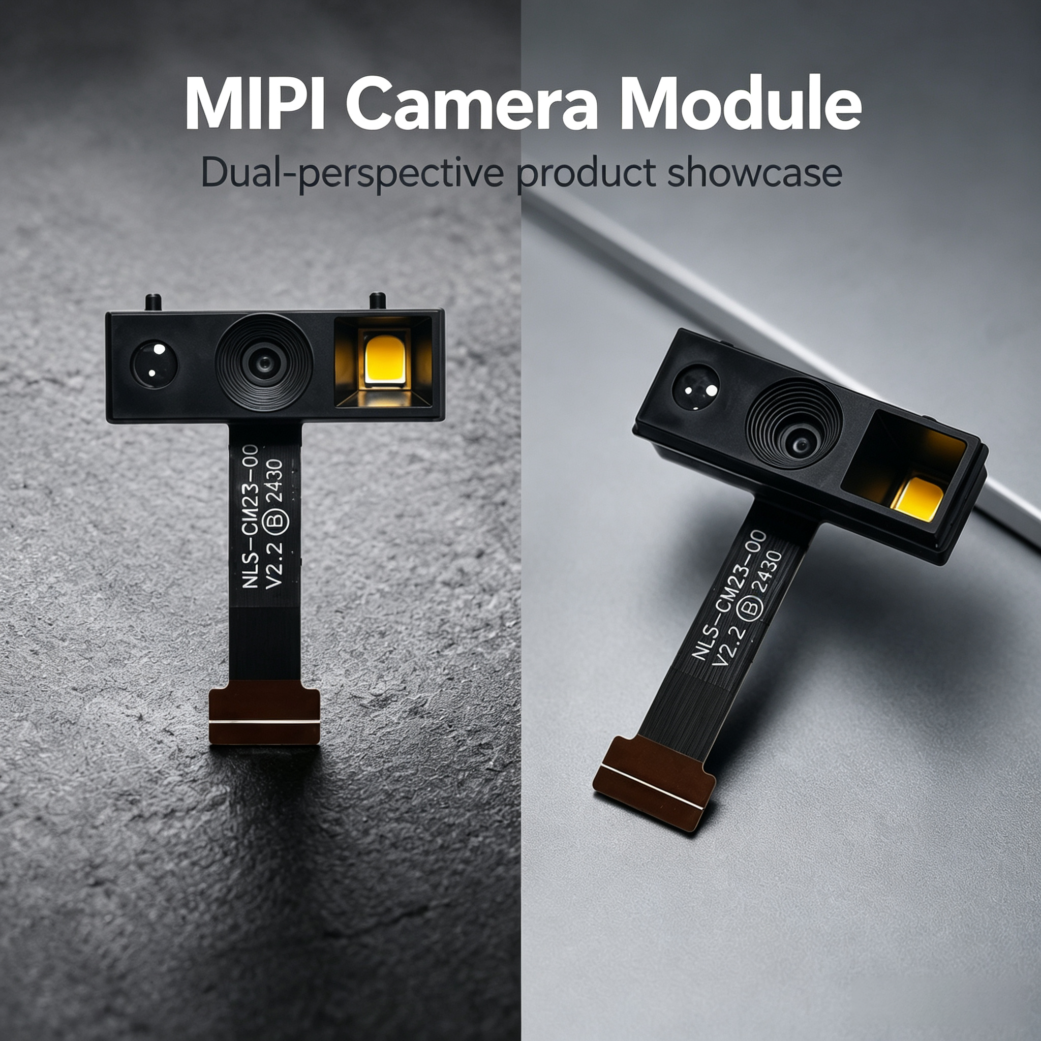
Selecting the right camera interface for your embedded vision system requires understanding the fundamental differences between two dominant technologies: the mipi camera module and the USB camera module. Both architectures serve vision-based applications, but they address different design priorities, power budgets, and integration constraints. This comparison goes beyond basic specifications to explore when each interface delivers real business value and where choosing wrong creates costly rework downstream.
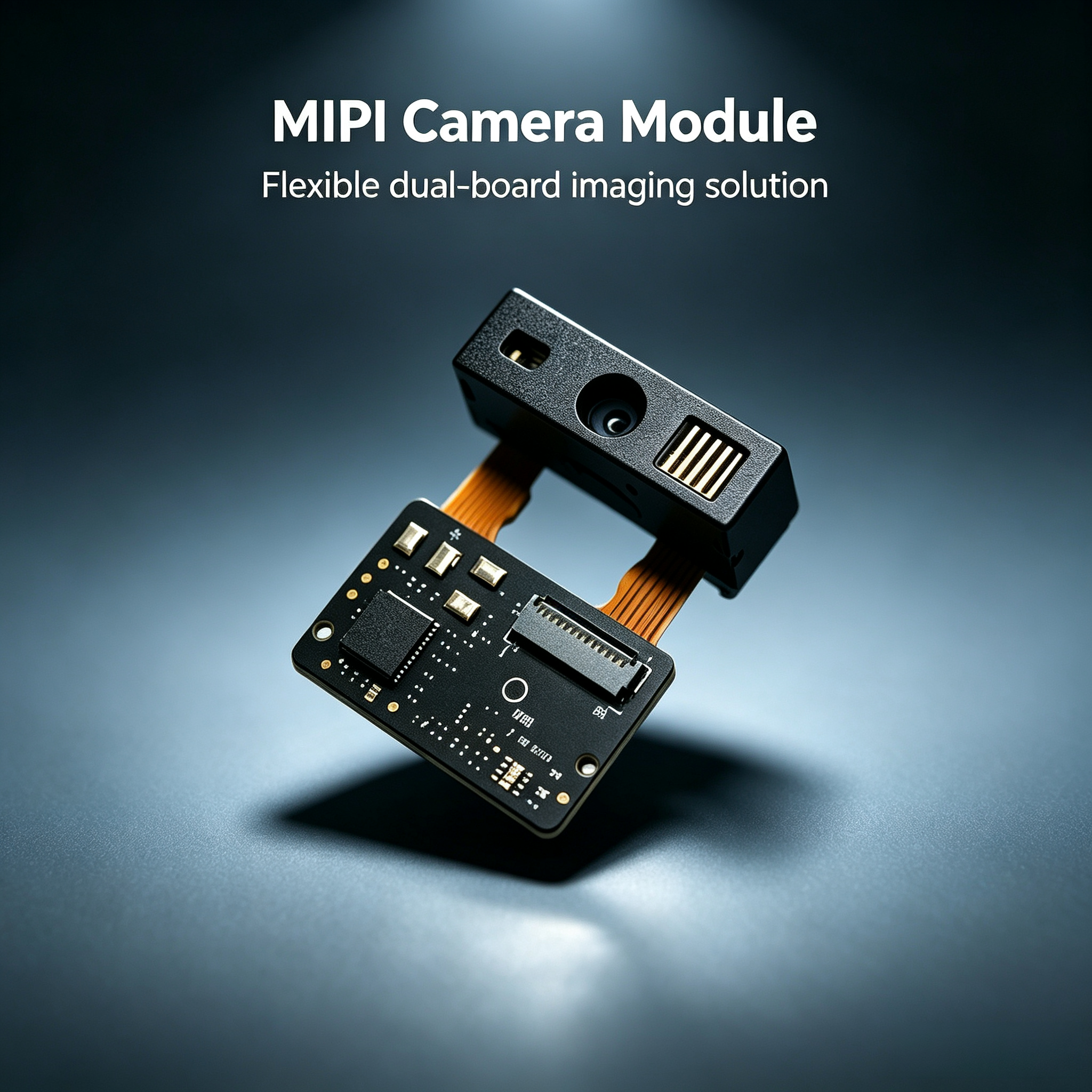
The usb vs mipi camera module decision shapes everything from power consumption and PCB layout complexity to processing latency and system scalability. Understanding these trade-offs early prevents mid-development conflicts between hardware architects, firmware engineers, and product managers. Each interface carries distinct advantages in specific deployment scenarios, and this guide maps the decision landscape with industrial clarity.
Architecture and Signal Transmission Fundamentals
MIPI Camera Module Protocol Structure
MIPI CSI-2 is a high-speed serial protocol designed specifically for mobile and embedded imaging systems. The mipi camera module transmits raw pixel data across dedicated differential pairs at speeds ranging from 80 Mbps to over 2 Gbps per lane, depending on the version and implementation. MIPI operates in a master-slave configuration where the SoC controls image capture timing, resolution, and frame rate through a separate I2C control bus, while video data flows over independent CSI lanes.
This separation of control and data paths creates efficiency gains that compound in power-constrained environments. The mipi camera module implementation avoids the continuous handshaking overhead present in USB bulk transfers, allowing sensors to enter low-power states between frames. Multi-lane configurations—typically 1, 2, or 4 lanes—provide scalability without protocol modification, letting system architects match bandwidth to actual application needs without overprovisioning.
USB Camera Module Data Flow and Topology
USB camera modules implement the USB Video Class specification, which layers image transmission over the USB bulk transfer protocol. Unlike the usb vs mipi camera module comparison reveals, USB is inherently a host-initiated, polling-based system. The host continually requests image frames, processes the request, retrieves data from the device buffer, and initiates the next transfer cycle. This transaction overhead remains constant regardless of whether you capture at 1 fps or 30 fps, creating efficiency losses in low-frame-rate applications.
USB camera modules benefit from standardized plug-and-play drivers and universal compatibility with consumer computing platforms. The ai vision mipi camera module advantage in power efficiency comes at the cost of this universality. USB requires negotiated bandwidth allocation, enumeration protocols, and descriptor parsing—layers of infrastructure that create determinism challenges for real-time vision pipelines in industrial settings.
Power Consumption and Thermal Considerations
Energy Efficiency in MIPI-Based Systems
Power consumption becomes the decisive factor in battery-powered and field-deployed systems. The mipi camera module architecture enables significantly lower power draw because the protocol supports dynamic bandwidth scaling and intelligent clock gating. When the system captures frames at lower resolution or reduced frame rate, the MIPI interface reduces serial clock speeds and lane activation, directly lowering supply current. An ai vision mipi camera module operating at 15 fps draws measurably less power than the same sensor connected via USB at the same frame rate.
Thermal dissipation improves alongside power reduction. MIPI-based edge devices in outdoor surveillance or agricultural monitoring applications maintain lower sensor and SoC junction temperatures, extending component life and reducing cooling infrastructure requirements. Power savings compound over deployment duration—a field device running for months accumulates meaningful reductions in battery replacement cycles or solar panel sizing requirements.
USB Module Power Overhead and Trade-offs
USB camera modules impose persistent power overhead through continuous host-device negotiation, even during idle periods. The USB interface maintains termination pull-ups, signal integrity monitoring, and protocol state machines that consume power independent of actual image transfer activity. For applications capturing intermittent snapshots rather than continuous video streams, usb vs mipi camera module power efficiency strongly favors MIPI designs. The power overhead becomes less critical in systems with external power supplies, but remains problematic for portable and IoT deployments.
Thermal considerations align with power trends. USB modules dissipate heat across the entire data path, including host controller silicon, cable resistance, and device circuitry. MIPI implementations concentrate heat dissipation in the SoC and sensor, allowing better localized cooling design. In compact industrial form factors, this distinction prevents thermal interference between imaging and processing subsystems.
Integration Complexity and System Design Implications
PCB Layout and Interface Routing
The mipi camera module interface requires careful high-speed differential pair routing, impedance matching, and crosstalk management. MIPI CSI-2 lanes operate at Gbps rates, demanding PCB trace length matching within tolerances and controlled via specifications. However, the mipi camera module footprint remains small because data traffic concentrates on 1 to 4 differential pairs plus control lines, reducing overall I/O pin count on the SoC. Signal integrity challenges are well-understood and routinely solved by reference designs from camera sensor and SoC vendors.
USB camera modules carry different routing complexity. The usb vs mipi camera module comparison shows USB demands longer cable runs, external hubs, and host controller PCB integration. While individual USB signal pairs are lower frequency than MIPI lanes, the added infrastructure—connector footprint, EMI shielding, and host silicon—consumes more board real estate. Legacy systems and consumer products often accommodate USB more readily because driver stacks are mature and widely understood, but custom industrial designs face integration overhead when USB adds constraints to mechanical packaging.
Firmware and Driver Development Overhead
Developing ai vision mipi camera module firmware requires embedded engineering expertise in CSI protocol details, sensor register programming, and SoC-specific camera controller configuration. The learning curve is steeper, but the mipi camera module development accelerates once team knowledge stabilizes. Reference implementations from sensor vendors and SoC manufacturers provide framework code, reducing custom development time. Firmware updates remain localized to the embedded device—no host driver compatibility layers needed.
USB camera modules shift development burden to the host side. Generic USB Video Class drivers handle the protocol layer, simplifying embedded firmware initially. However, custom vision algorithms, metadata injection, and frame-precise triggering require careful driver-level integration. When cross-platform compatibility matters (Windows, Linux, macOS), USB driver maintenance becomes fragmented. The mipi camera module avoids this multiplicity because MIPI is inherently embedded-native, collapsing the firmware surface to one platform target.
Performance and Real-Time Constraints
Latency in MIPI Pipeline
MIPI CSI-2 delivers lower end-to-end latency because data flows directly from sensor to SoC image signal processor without USB protocol overhead. Frame capture and processing initiate in lockstep with sensor output, creating deterministic timing behavior essential for real-time applications like autonomous robotics and quality inspection systems. The mipi camera module also supports frame synchronization across multiple sensors—critical for stereo vision and multi-camera tracking systems where temporal alignment prevents 3D reconstruction errors.
Latency variability in USB implementations stems from host scheduling, interrupt prioritization, and buffer management. USB bulk transfers complete only when the host scheduler grants bandwidth, introducing jitter that corrupts motion estimation and tracking algorithms. For safety-critical applications requiring bounded response time, the usb vs mipi camera module comparison strongly favors MIPI's predictable, interrupt-driven data flow.
Bandwidth Utilization and Scalability
Multi-lane MIPI CSI-2 implementations support simultaneous high-resolution capture and processing with minimal CPU load. A mipi camera module carrying 4K video at 60 fps consumes predictable bandwidth, leaving processor resources for vision algorithms. USB 2.0 bandwidth limitations become problematic—high-resolution streams require careful compression trade-offs between quality and CPU overhead. USB 3.0 and 3.1 improve capacity, but older embedded systems and industrial control platforms rarely integrate USB 3 host controllers, limiting practical deployment.
Scalability to multi-camera systems favors MIPI. Adding a second ai vision mipi camera module simply activates additional CSI lanes or connects to a second SoC interface—both architectures support parallel streams natively. USB multiplexing via hubs introduces latency imbalance and requires powered infrastructure, complicating field deployment and maintenance.
FAQ
When should I choose a MIPI camera module over USB?
Choose the mipi camera module for battery-powered devices, real-time embedded systems, and applications requiring frame-precise synchronization. MIPI excels in edge AI vision systems, autonomous robotics, and industrial inspection where low latency and power efficiency directly impact business outcomes. If your SoC supports CSI-2 natively and your system design embraces embedded processing rather than PC-based analysis, the mipi camera module delivers superior total-cost-of-ownership through reduced power consumption and firmware simplification.
What are the main disadvantages of MIPI compared to USB?
The mipi camera module requires higher embedded engineering expertise and SoC-level integration planning. If your platform lacks native CSI support, adding MIPI controllers adds cost. Generic consumer drivers do not exist—each SoC vendor provides proprietary camera implementations. The usb vs mipi camera module trade-off becomes clear when evaluating team skills: MIPI demands deeper embedded systems knowledge, while USB suits teams with primarily applications-level experience.
Can I migrate from USB to MIPI without redesigning my entire system?
Migrating from USB to an ai vision mipi camera module requires SoC-level changes because MIPI support must exist at silicon level. However, if you separate your vision processing module from your main application processor, migrating the camera interface while retaining the host CPU becomes feasible. Camera abstraction layers in firmware allow substituting camera drivers without rewriting upper vision layers. Planning modular architecture early makes technology evolution possible; retrofitting integration always costs more than forward design.